Lab 2: Interrupts, Timers
Useful Chapters from Datasheet ATmega324
- 1. Pin Configurations
- Section 1.1 - Page 2
- 7. AVR CPU Core
- Section 7.3 - Page 11
- Section 7.7 - Page 16
- 12. Interrupts
- Table 12-1 - Page 61
- 13. External Interrupts
- Section 13.1 - Page 67
- Sections 13.2.4-13.2.9 - Page 69
- 16. 16-bit Timer/Counter1 and Timer/Counter3 with PWM
- Sections 16.1-16.3 - Page 111
- Section 16.5 - Page 117
- Section 16.7 - Page 120
- Sections 16.9.1-16.9.2 - Page 123
- Section 16.11 - Page 132
The chapters are from Datasheet ATmega324, a document available on the desktop of the laboratory computers.
The chapter order might be different in other versions of the datasheet!
Objective
This lab aims to familiarize you with hardware interrupts and timers in the ATmega324 microcontroller.
In this session, we will use timers only for counting, without generating PWM signals.
PWM functionality will be explored in the next laboratory.
1. Interrupts
A hardware interrupt is a synchronous or asynchronous signal from a peripheral indicating the occurrence of an event that the processor must handle.
Handling an interrupt suspends the normal execution flow of a program and triggers the execution of an Interrupt Service Routine (ISR).
Why Use Interrupts?
Interrupts eliminate the need for polling loops where a processor constantly checks for an event from a peripheral.
By using interrupts:
- Peripherals can notify the processor only when necessary.
- The processor is free to execute other tasks until an event occurs.
- The program executes more efficiently.
Handling Interrupts
Before executing an ISR, the processor saves its current state:
- Program Counter (PC)
- Status registers
- Variables affected by the ISR execution
This information is stored in memory, typically a stack.
Once the ISR completes, the previous state is restored, and the main program resumes from where it was interrupted.
Interrupt Vector Table (IVT)
To associate an interrupt with a specific ISR function, the processor uses an Interrupt Vector Table (IVT), shown in the diagram below.
Each interrupt is assigned a fixed memory address where its ISR function is located.
When an interrupt occurs, the processor jumps to its corresponding ISR address in the IVT.
Interrupt Priority:
- Lower addresses → Higher priority
- Interrupts at the beginning of the IVT are handled first.
Interrupt Vector Table for ATmega324
| Vector No. | Program Address | Source | Interrupt Definition |
|---|---|---|---|
| 1 | 0000 | RESET | External Pin, Power-on Reset, Brown-out Reset, Watchdog Reset, and JTAG AWR Reset |
| 2 | 0002 | INT0 | External Interrupt Request 0 |
| 3 | 0004 | INT1 | External Interrupt Request 1 |
| 4 | 0006 | INT2 | External Interrupt Request 2 |
| 5 | 0008 | PCINT0 | Pin Change Interrupt Request 0 |
| 6 | 000A | PCINT1 | Pin Change Interrupt Request 1 |
| 7 | 000C | PCINT2 | Pin Change Interrupt Request 2 |
| 8 | 000E | PCINT3 | Pin Change Interrupt Request 3 |
| 9 | 0010 | WDT | Watchdog Time-out Interrupt |
| 10 | 0012 | TIMER2_COMPA | Timer/Counter2 Compare Match A |
| 11 | 0014 | TIMER2_COMPB | Timer/Counter2 Compare Match B |
| 12 | 0016 | TIMER2_OVF | Timer/Counter2 Overflow |
| 13 | 0018 | TIMER1_CAPT | Timer/Counter1 Capture Event |
| 14 | 001A | TIMER1_COMPA | Timer/Counter1 Compare Match A |
| 15 | 001C | TIMER1_COMPB | Timer/Counter1 Compare Match B |
| 16 | 001E | TIMER1_OVF | Timer/Counter1 Overflow |
| 17 | 0020 | TIMER0_COMPA | Timer/Counter0 Compare Match A |
| 18 | 0022 | TIMER0_COMPB | Timer/Counter0 Compare Match B |
| 19 | 0024 | TIMER0_OVF | Timer/Counter0 Overflow |
| 20 | 0026 | SPI_STC | SPI Serial Transfer Complete |
| 21 | 0028 | USART0_RX | USART0 Rx Complete |
| 22 | 002A | USART0_UDRE | USART0 Data Register Empty |
| 23 | 002C | USART0_TX | USART0 Tx Complete |
| 24 | 002E | ANALOG_COMP | Analog Comparator |
| 25 | 0030 | ADC | ADC Conversion Complete |
| 26 | 0032 | EE_READY | EEPROM Ready |
| 27 | 0034 | TWI | Two-Wire Serial Interface |
| 28 | 0036 | SPM_READY | Store Program Memory Ready |
| 29 | 0038 | USART1_RX | USART1 Rx Complete |
| 30 | 003A | USART1_UDRE | USART1 Data Register Empty |
| 31 | 003C | USART1_TX | USART1 Tx Complete |
| 32 | 003E | TIMER3_CAPT | Timer/Counter3 Capture Event |
| 33 | 0040 | TIMER3_COMPA | Timer/Counter3 Compare Match A |
| 34 | 0042 | TIMER3_COMPB | Timer/Counter3 Compare Match B |
| 35 | 0044 | TIMER3_OVF | Timer/Counter3 Overflow |
From the table above, besides internal component interrupts (timers, serial interfaces, analog-to-digital converters), there are also external peripheral interrupts:
✅ INT0-INT2
✅ PCINT0-PCINT3
The difference between these two types of external interrupts lies in their capabilities and level of granularity.
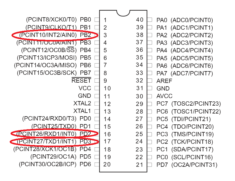
INTn Interrupts
- Signals for INTn interrupts come from:
- Port D (pins 2, 3)
- Port B (pin 2)
- They can trigger an interrupt:
- On rising or falling edge
- Or on level 0, depending on the configuration.
PCINTn Interrupts
- PCINTn interrupts trigger on both edges (hence the name Pin Change INTerrupt).
- 8 pins are multiplexed onto a single interrupt.
- While PCINT signals can be individually enabled, the exact pin that triggered the interrupt must be determined by checking the PINn register.
- Multiple simultaneous pin changes cannot be distinguished.
For pin change interrupts, do not confuse the interrupt vector (e.g., PCINT0) with the actual interrupt (e.g., PCINT0 (PA0)).
The mapping between vectors and interrupts is found in Section 30, Page 555 of the datasheet.
External Interrupt Pins on ATmega324
When an interrupt occurs, besides saving the state, the processor disables interrupts, and upon returning from the interrupt handler, it re-enables them.
Interrupts can also be manually re-enabled within the handler (e.g., if we are inside a handler for receiving a frame over a serial interface and want to enable a timer interrupt).
1.1. Using Interrupts
To enable an interrupt, follow these steps:
1️⃣ Enable the global interrupt mechanism
Interrupt handling must be explicitly enabled (bit I - Global Interrupt Enable in the SREG register).
To set and clear this bit, use the following helper functions:
// Enable interrupts
sei();

// Disable interrupts
cli();
2️⃣ Configure the peripheral that will generate interrupts
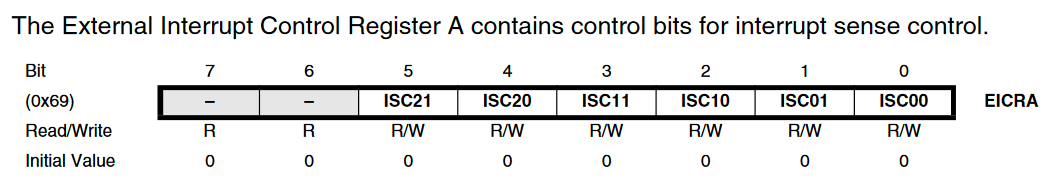
For example, INT0, INT1, and INT2 are configured via the EICRA register
(External Interrupt Control Register A, section 13.2.1, page 67 in datasheet.
For pin change interrupts, use the PCICR register.
EICRA Register
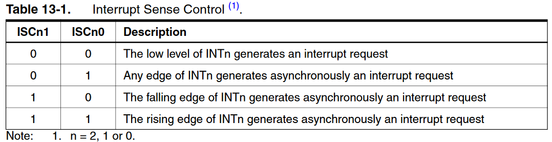
Interrupt Trigger Modes
Configuration Examples
// External interrupt: Set INT0 to trigger on ANY logic change
EICRA |= (1 << ISC00);

// Pin change interrupt: Enable the pin change interrupt, set PCIE1 to enable PCMSK1 scan
PCICR |= (1 << PCIE1);
An external interrupt can be configured to trigger on:
- Rising edge
- Falling edge
- Any level change
📌 See Table 13-1 in the datasheet for details.
📌 Pin change interrupts trigger on any level change, so the signal value must be explicitly checked in the handler.
3️⃣ Implement the Interrupt Service Routine (ISR)
Interrupt handlers must be mapped to fixed memory addresses in the interrupt vector table.
Use the ISR() macro to define them, passing the appropriate interrupt type.
Example: Handling INT0 and PCINT1 interrupts
ISR(INT0_vect) {
  // Code for external interrupt
}

ISR(PCINT1_vect) {
  // Code for pin change interrupt

  if ((PINB & (1 << PB1)) == 0) {
     // Interrupt triggered by pin PB1
  }
}
Enabling Interrupts and Testing the Program
To enable external interrupts, configure the External Interrupt Mask Register (EIMSK):
- Bits INT2:0 control whether external interrupts (INT0-INT2) are enabled.
For pin change interrupts, configure the corresponding register (e.g., PCMSK1 for pin change interrupts on specific pins).
// Enable external interrupt INT0
EIMSK |= (1 << INT0);

// Enable pin change interrupt PCINT9 (PB1)
PCMSK1 |= (1 << PCINT9);

// Enable global interrupts
sei();
📌 Additional Registers for Interrupt Management
For a complete description of these registers, see the datasheet
(Interrupts, External Interrupts chapters).
Status Register (SREG)
- Stores status flags set by the ALU.
- Contains I bit, which enables/disables global interrupts.
- Not saved when an interrupt occurs.
- Described in the AVR CPU Core chapter.
📌 SREG Register

MCU Control Register (MCUCR)
IVSELbit: Determines the placement of the interrupt vector table
(0= Flash memory start,1= Boot Loader section).IVCEbit: Enables writing to theIVSELbit.
📌 MCUCR Register

External Interrupt Mask Register (EIMSK)
- Bits INT2:0 control whether external interrupts are enabled.
- If
INT2:0AND theIbit inSREGare set to1,
external interrupts are enabled on the corresponding pin.
1.2 Using Interrupts in avr-gcc
The avr-libc library provides the <avr/interrupt.h> interface
for defining interrupt service routines (ISRs).
Each microcontroller has a specific vector table,
declared in the corresponding IO header file
(for ATMega324, see iom324.h).
Common Interrupt Vectors
| Interrupt | Vector | Description |
|---|---|---|
| TIMER1_COMPA | TIMER1_COMPA_vect | Compare Match on Timer 1, Threshold A |
| TIMER1_COMPB | TIMER1_COMPB_vect | Compare Match on Timer 1, Threshold B |
| TIMER1_OVF | TIMER1_OVF_vect | Timer 1 Overflow |
| PCINT1 | PCINT1_vect | Pin Change Interrupt on Port B |
| ... | ... | ... |
Defining an ISR
Use the ISR() macro to create an interrupt handler:
#include <avr/interrupt.h>

ISR(INT0_vect) {
    // Interrupt handling code
}
Interrupt Handling Rules
✅ No return value: The processor resumes execution where it left off
✅ Keep execution time short: The ISR blocks main program execution
✅ Handle shared variables carefully:
- Use
volatilefor shared variables, so the compiler does not optimize them away. - Beware of race conditions when modifying multi-byte (16/32-bit) variables.
📌 Interrupts can be declared with specific flags
#include <avr/interrupt.h>

ISR(vector, flag) {
    // Interrupt handling code
}
The ISR() macro:
- Defines the handler for a specific peripheral.
- Saves the
SREGregister before execution. - Calls the
retiinstruction when finished.
ISR Flags
| Flag | Description |
|---|---|
| ISR_BLOCK | Default behavior: Global interrupts are disabled inside the ISR. |
| ISR_NOBLOCK | Allows nested interrupts (useful for prioritizing interrupts). |
| ISR_NAKED | Omits prologue/epilogue (no SREG save, no reti call). |
| ISR_ALIASOF | Makes an ISR alias of another ISR. |
Example: Aliasing Interrupts
#include <avr/interrupt.h>

ISR(INT0_vect) {
    // INT0 interrupt handler
}

ISR(INT1_vect, ISR_ALIASOF(INT0_vect)) {
    // INT1 uses the same handler as INT0
}
Additional Helper Functions
| Function | Description |
|---|---|
sei() | Enables global interrupts (I bit in SREG = 1). |
cli() | Disables global interrupts (I bit in SREG = 0). |
reti() | Returns from an ISR, re-enabling interrupts. |
⚠ Active interrupts without an ISR will trigger a system Reset!
If an enabled interrupt has no handler, the system will reset.
2. Timer
2.1. How a Timer Works
A Timer/Counter measures fixed time intervals and can trigger interrupts when the measured interval expires.
Once initialized, a timer operates independently from the CPU, eliminating the need for delay loops.
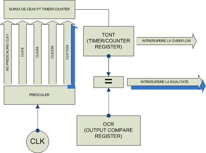
Basic Timer Components in ATmega324
- Counter Register (
TCNT) - Measures time intervals and increments at a defined frequency. - Prescaler - Divides the clock frequency based on the application's needs.
- Compare Register (
OCRn) - Stores a threshold value. IfTCNTmatches this value, an interrupt is generated.
📌 Timer Functional Diagram (ATmega324)
ATmega324 has three timers:
- Two 8-bit timers (Timer0 & Timer2)
- One 16-bit timer (Timer1)
Timers can also operate in PWM mode to generate variable voltage control signals, which will be explored in the next lab.
2.2. Timer Operating Modes
Timers can operate in various modes, each defining:
- The counting range.
- Counting behavior (increment-only or increment/decrement).
- When the counter resets.
📌 Modes used in this lab:
| Mode | Description | Counter Behavior | Properties |
|---|---|---|---|
| Normal | Starts at 0 Counts up to 0xFFFF |  | Fixed frequency based on clock & prescaler |
| CTC (Clear Timer on Compare) | Starts at 0 Counts until reaching OCRnA Resets when threshold is met |  | Variable frequency based on clock, prescaler & compare value |
Key Terms:
- BOTTOM: Minimum counting value (
0). - TOP: Maximum counting value.
- MAX: Highest possible value (255 for 8-bit, 65535 for 16-bit timers).
- TOP = MAX in Normal Mode.
2.3. Timer Registers
| Timer | Registers | Description |
|---|---|---|
| Timer0 (8-bit) | TCNT0 | Counter register (holds current count value) |
TCCR0A, TCCR0B | Control registers (configure the timer) | |
OCR0A, OCR0B | Compare registers (set interrupt thresholds) | |
TIMSK0, TIFR0 | Registers for enabling/disabling interrupts & status flags | |
| Timer1 (16-bit) | TCNT1H/L | 16-bit counter register |
TCCR1A, TCCR1B, TCCR1C | Control registers | |
OCR1AH/L, OCR1BH/L | 16-bit compare registers | |
TIMSK1, TIFR1 | Interrupt & flag registers | |
ICR1H/L | Input Capture Register - stores counter value on an external event | |
| Timer2 (8-bit) | Same registers as Timer0 | Timer2 supports an external clock via TOSC1 & TOSC2 |
ASSR, GTCCR | Registers for asynchronous operation |
Interrupts must be globally enabled (bit I in SREG must be set).
Use sei(); to enable global interrupts.
2.4. Configuring the Timer
Setting the Timer Mode
To configure a timer mode:
- Set the
WGMbits in the corresponding TCCRnA register. - Define the compare threshold.
Example: Set Timer0 in CTC Mode, counting to 5
TCCR0A |= (1 << WGM01); // Set CTC Mode
OCR0A = 5;              // Set compare threshold
Configuring the Prescaler
Prescaler values are set using CSx bits in TCCRnB.
Example: Set Timer2 prescaler to 256
TCCR2B |= (1 << CS22) | (1 << CS21); // Set prescaler to 256
Enabling Timer Interrupts
To trigger an interrupt on compare match, enable the corresponding bit in TIMSKx.
Example: Enable Compare Match A interrupt for Timer1
#include <avr/interrupt.h>

ISR(TIMER1_COMPA_vect) {
  // Timer1 Compare Match A Interrupt Handler
}

void init_timer1() {
  TIMSK1 |= (1 << OCIE1A); // Enable Timer1 Compare Match A Interrupt
}

int main() {
  sei();         // Enable global interrupts
  init_timer1(); // Initialize Timer1
  while (1) {
    // Main loop
  }
}
2.5. Handling 16-bit Registers
Some registers (TCNT1, OCR1A/B, ICR1) are 16-bit but accessed 8-bits at a time.
- Writing high byte first ensures atomic updates.
Example: Writing to OCR1A (16-bit register)
OCR1AH = (threshold >> 8); // Write high byte first
OCR1AL = threshold;        // Write low byte
This is automatically handled by the compiler in C when accessing registers without H or L suffix.
2.6. Timer Calculator
To configure a timer:
- Choose a prescaler.
- Set a count limit.
- Calculate values based on desired frequency and system clock.
Formula for Interrupt Frequency (f_int):
f_int = f_clk / (prescaler * (tc + 1))
Calculate Timer Count (tc):
tc = f_clk / (prescaler * f_int) - 1
📌 Example: Generating a 1Hz Timer Interrupt (Clock = 12MHz)
| Prescaler | Counter Limit (tc) | Timer1 (16-bit) | Timer0,2 (8-bit) | Notes |
|---|---|---|---|---|
| 1 | 11,999,999 | ❌ Invalid (16-bit overflow) | ❌ Invalid (8-bit overflow) | Overflow |
| 8 | 1,499,999 | ❌ Invalid | ❌ Invalid | Overflow |
| 64 | 187,499 | ❌ Invalid | ❌ Invalid | Overflow |
| 256 | 46,874 | ✅ Valid (Use Timer1) | ❌ Invalid | Timer1 required |
| 1024 | 11,717 | ❌ Invalid | ❌ Invalid | Not exact/divisible |
Timer2 supports prescalers of 32 and 128 (See ATmega324 Datasheet, Section 17.11.2, Page 160).
Useful Online Timer Calculators
If you need precise register values, use these tools:
- ATmega Timer/Counter/Prescaler Calculator
ATmega Timer Calculator
- Arduino Timer Interrupts Calculator
AVR Timer Calculator
3. Exercises
- Lab Work
- Homework
Task 1.1: Implementing millis()
- Implement a function similar to Arduino's
millis(), which returns the elapsed time since the microcontroller (µC) started or was last reset. - Configure USART0 with the same parameters as in the previous lab.
- Send a chosen message to the PC every 1 second.
📌 Hints:
- The µC clock frequency is 12MHz.
- Use the formulas from the previous section to calculate the prescaler and compare register value for the timer.
- Timer2 has more prescaler options, making it a good choice.
To print messages to serial, use these functions.
void USART0_init(uint32_t baud)
{
    UCSR0B = 0; // Disable interrupts, TX, RX
    UCSR0A = 0; // Clear flags
    UCSR0C = 0; // Reset mode (async, 8N1)
    UBRR0H = 0; // Clear baud rate high byte
    UBRR0L = 0; // Clear baud rate low byte

    uint16_t ubrr = (uint16_t)(F_CPU / (16UL * baud) - 1UL);

    UBRR0H = (uint8_t)(ubrr >> 8);
    UBRR0L = (uint8_t)(ubrr & 0xFF);

    UCSR0A = 0;
    UCSR0B = (1 << TXEN0);                        // enable TX
    UCSR0C = (1 << UCSZ01) | (1 << UCSZ00);       // 8N1
}

void USART0_transmit(char data)
{
    while (!(UCSR0A & (1 << UDRE0))) {;}
    UDR0 = data;
}

void USART0_print(const char *s)
{
    while (*s) {
        USART0_transmit(*s++);
    }
}

void USART0_print_u32(uint32_t value)
{
    char buf[11];
    uint8_t i = 10;

    buf[i] = '\0';

    if (value == 0) {
        USART0_transmit('0');
        return;
    }

    while (value > 0 && i > 0) {
        buf[--i] = '0' + (value % 10);
        value /= 10;
    }

    USART0_print(&buf[i]);
}
Task 1.2: Button Debouncing
- A debounce method is required to properly detect short button presses.
- How can
millis()be used to eliminate false readings? - Write a pseudocode function illustrating your solution.
Task 2: Reimplementing Lab 0 Exercise 3 Using Timers & Interrupts
- Use timers & interrupts to read button presses and control LED blinking.
📌 Reminder (Lab 0, Exercise 3):
- BTN1: Cycles the RGB LED color (Red → Green → Blue → Red).
- BTN2: Toggles LED blinking.
Task 3: Controlling a Buzzer with Buttons
- Use buttons
PD6andPB2to control a buzzer. - One button selects the frequency from three values (e.g., 100Hz, 200Hz, 300Hz).
- The second button must be held down for the buzzer to produce sound.
- Use the RGB LED to indicate the selected frequency.
Task 4 (BONUS): Timer Error Correction
- The
millis()function accumulates error over time due to clock frequency division inaccuracies. - Calculate:
- After how many timer cycles does the error exceed 1ms?
- Propose a method to reduce this error.
- Implement the proposed correction method.
Use this Tinkercad homework skeleton ↗️
Task 1.1: Implementing millis()
- Implement a function similar to Arduino's
millis(), which returns the elapsed time since the microcontroller (µC) started or was last reset. - Configure USART0 with the same parameters as in the previous lab.
- Send a chosen message to the PC every 1 second.
📌 Hints:
- The µC clock frequency is 12MHz.
- Use the formulas from the previous section to calculate the prescaler and compare register value for the timer.
- Timer2 has more prescaler options, making it a good choice.
Task 1.2: Button Debouncing
- A debounce method is required to properly detect short button presses.
- How can
millis()be used to eliminate false readings? - Write a pseudocode function illustrating your solution.
Task 2: Reimplementing Lab 0 Exercise 3 Using Timers & Interrupts
- Use timers & interrupts to read button presses and control LED blinking.
📌 Reminder (Lab 0, Exercise 3):
- BTN1: Cycles the RGB LED color (Red → Green → Blue → Red).
- BTN2: Toggles LED blinking.
Task 3: Controlling a Buzzer with Buttons
- Use buttons
PD6andPB2to control a buzzer. - One button selects the frequency from three values (e.g., 100Hz, 200Hz, 300Hz).
- The second button must be held down for the buzzer to produce sound.
- Use the RGB LED to indicate the selected frequency.
Task 4 (BONUS): Timer Error Correction
- The
millis()function accumulates error over time due to clock frequency division inaccuracies. - Calculate:
- After how many timer cycles does the error exceed 1ms?
- Propose a method to reduce this error.
- Implement the proposed correction method.