Lab 5: SPI (Serial Peripheral Interface)
1. Introduction
In this lab, we’ll explore the SPI communication protocol, widely used in embedded systems for data exchange between two or more devices. The final objective will be to build an audio player on the lab board that reads .wav files from an SD card and plays them using the onboard speaker.
2. SPI Protocol (Serial Peripheral Interface)
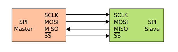
SPI is a synchronous communication standard developed by Motorola. It operates in full-duplex mode (data transfer happens simultaneously in both directions).
Communication is based on a Master-Slave architecture (one Master device and one or more Slaves). The Master always initiates communication.
SPI is also known as a four-wire protocol due to its use of four separate lines:
- MOSI — Master Out Slave In (data from Master to Slave)
- MISO — Master In Slave Out (data from Slave to Master)
- SCLK — Serial Clock (clock signal generated by the Master)
- CS / SS — Chip Select / Slave Select (used by the Master to select the Slave; active LOW)
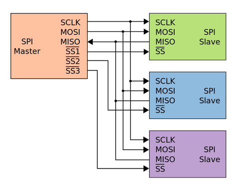
2.1 Connecting Multiple Slaves
Multiple Slave devices can be connected to a single Master. The MOSI, MISO, and SCLK lines are shared, while each Slave has a separate CS / SS line.
When the Master wants to communicate with a particular Slave, it sets the corresponding CS / SS line to LOW (active). All other SS lines remain HIGH, and those Slaves ignore communication.
3. Data Transmission in SPI
To begin communication:
- The Master sets the clock frequency (must not exceed the Slave's max supported rate).
- It selects the Slave by setting its CS / SS line LOW.
During each SPI clock cycle (full-duplex):
- The Master sends a bit via MOSI, and the Slave reads it.
- The Slave simultaneously sends a bit via MISO, which the Master reads.
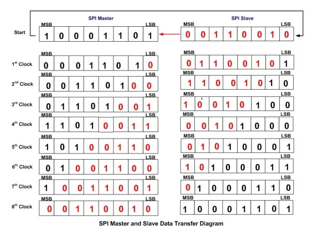
This is usually done through circularly connected shift registers in both Master and Slave.
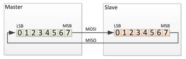
Typically:
- The most significant bit (MSB) is sent first.
- After one word is transmitted, both devices will have exchanged the entire contents of their shift registers.
Once data transmission is complete:
- The Master stops the clock signal (SCLK).
- It deactivates the Slave by setting the associated CS / SS line to HIGH.
Note: All unselected Slaves ignore clock and MOSI lines and don’t drive the MISO line. Only one Slave can be selected at a time by the Master.
4. SPI on ATMega324
The ATMega324 microcontroller provides users with an SPI interface that can operate in both Master and Slave modes.
As usual, configuring and using this interface involves working with control, status, and data registers.
The full description of the SPI-related registers can be found in the ATmega324P Datasheet, Chapter: SPI – Serial Peripheral Interface (starting on page 214).
Below is a brief overview of the most important SPI registers and fields:
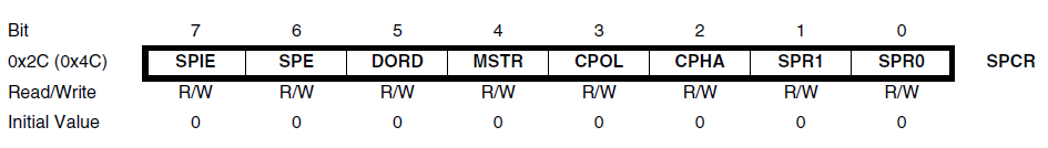
SPI Control Register (SPCR)
| Bit | Name | Description |
|---|---|---|
| 6 | SPE | SPI Enable — Set to 1 to enable the SPI interface |
| 5 | DORD | Data Order — 1: LSB transmitted first, 0: MSB first |
| 4 | MSTR | Master/Slave Select — 1: Master mode, 0: Slave mode |
| 3-0 | CPOL, CPHA, SPR1, SPR0 | Clock polarity, phase, and frequency selection |
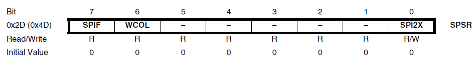
SPI Status Register (SPSR)
| Bit | Name | Description |
|---|---|---|
| 7 | SPIF | SPI Interrupt Flag — Set to 1 when a transfer is complete |
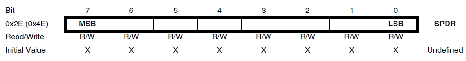
SPI Data Register (SPDR)
The SPDR register is used to both transmit and receive data:
- Writing to this register starts a new transmission (in Master mode).
- Reading from it gives you the data received via SPI.
5. FAT SD Card
The lab board includes an SD card reader that communicates with the ATMega324 microcontroller via the SPI protocol — which is the main use case for today’s lab.
The diagram below shows how the SD card reader is connected to the microcontroller. Notice that some of the pins we've already used in past labs are reused here for SPI signals.

SD Card Format: FAT32
The SD cards we'll be working with are formatted using the FAT32 file system. To simplify file operations, we’ll use the Petit FAT Filesystem library — chosen for its small footprint (2–4 KB) and minimal RAM usage (just 46 bytes plus stack).
Petit FAT Filesystem API
Here are the main functions provided by the library:
FRESULT pf_mount (FATFS*);                   // Mount or unmount a volume
FRESULT pf_open (const char*);               // Open a file
FRESULT pf_read (void*, WORD, WORD*);        // Read data from a file
FRESULT pf_write (const void*, WORD, WORD*); // Write data to a file
FRESULT pf_lseek (DWORD);                    // Move file pointer
FRESULT pf_opendir (DIR*, const char*);      // Open a directory
FRESULT pf_readdir (DIR*, FILINFO*);         // Read from a directory
These functions allow low-level file access from an embedded system — exactly what we need to implement a basic audio player on our microcontroller board.
6. Exercises
- Lab Work
- Homework
📥 Download the starter code archive:
lab5_skel.zip
In this lab, you won’t be writing a lot of code, but it’s important to understand how your code interacts with the skeleton and the behavior of the library functions you’ll use.
Task 1: SPI Control (2p)
Implement the basic SPI communication functions in spi.c:
SPI_init()SPI_exchange()
- Configure PB4 (SS) as output and set it to HIGH to disable SPI interrupt triggering via slave select.
- Follow examples from page 217 of the datasheet.
- Refer to section 5's wiring diagram to identify MOSI and SCLK pins.
- Set SPI to Master mode with SCLK = fosc/16 (slower frequency for SD card compatibility).
- Remember to use register names with a
0suffix:SPCR0,SPDR0, etc. - Use
SPDR0to send data and receive the response in one function (full-duplex), replacing the need forSPI_read()andSPI_write().
Task 2: SD Card Control (2p)
In sd.c, implement:
SD_init()SD_receive()SD_transmit()
- PA2 (SS for SD card) must be set as output. Leave the HIGH/LOW handling to the skeleton code.
- Use
SPI_exchange()for both transmitting and receiving. - In
SD_receive(), send 0xFF as a dummy byte to initiate a read (Master must always initiate). - ✅ Checkpoint: After flashing your code, the LCD should change from
Mounting...toMounted!. If not, hit the RESET button and debug if needed.
CHECKPOINT (1p)
After a few seconds, the LCD should display: "Mounted!"
This confirms that the SD card has been successfully initialized and mounted.
Task 3 – Reading Temperature (2p)
Set up the ADC and read temperature from an analog sensor (e.g., LM35).
Implementation steps:
- Create and implement
adc_init()andadc_read() - Configure:
- Reference Voltage: AVcc
- ADC Prescaler: 8
- Convert ADC value to voltage, then to °C (e.g.,
temp = voltage * 100) - Display the temperature on the LCD
- Also send the temperature reading via USART (serial)
Task 4 – Logging Temperature to SD Card (2p)
Implement log_temperature() in lab5.c to save temperature readings to a CSV file.
Requirements:
- Use
SD_log_data()to write data to the file - Show current temperature on the LCD
- Send current temperature via USART
- When button PD6 is pressed, append a new log entry to the file
Task 5 – Navigating Log Entries (2p)
Implement init_log_display() and next_log_entry() to read the file log.csv line by line.
Features:
- Display each CSV line (entry) on the LCD
- On PB2 button press, move to the next line
- When reaching the end, loop back to the start
CHECKPOINT (1p)
You must be able to scroll through all temperature logs using the button.
Once complete, your logger should support:
- Real-time sensor readings
- Data logging on button press
- Full log navigation via the LCD and button
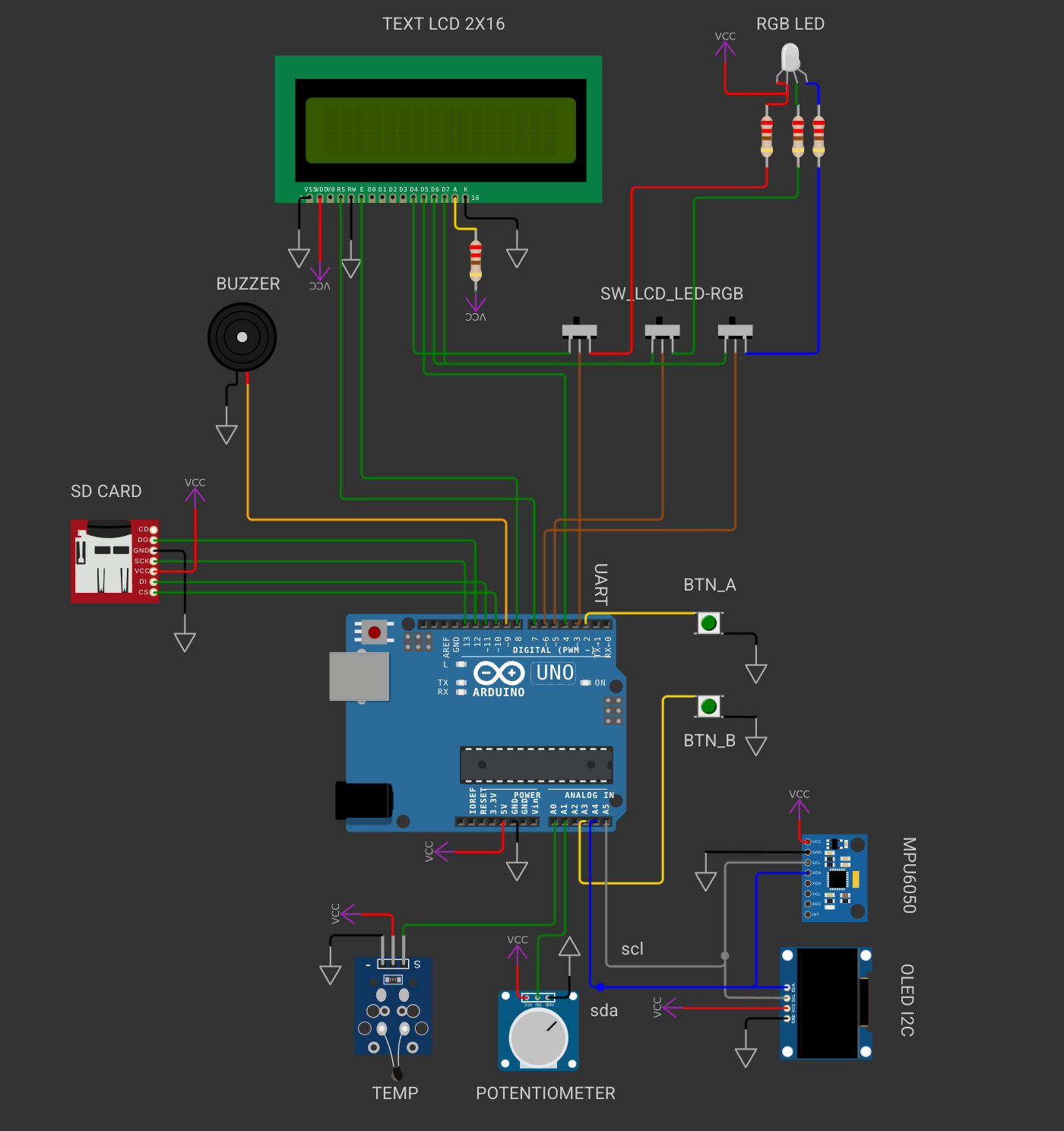
From now on you will be working with Wokwi because its easier to import libraries. The 📥homework skeleton will be the same for all the labs. You don't need to modify the circuit for the homework. You will only change the .c and .h files. The connections to the peripherals wil be different from the ones in the lab development board. For the homework you will work with Arduino Uno (ATmega328P).
Make sure to read the README.md before solving the exercises.
Task 1: SPI Control (2p)
Implement the basic SPI communication functions in spi.c:
SPI_init()SPI_exchange()
- Configure (SS) as output and set it to HIGH to disable SPI interrupt triggering via slave select.
- Follow examples from page 217 of the datasheet.
- Refer to section 5's wiring diagram to identify MOSI and SCLK pins.
- Set SPI to Master mode with SCLK = fosc/16 (slower frequency for SD card compatibility).
- Remember to use register names with a
0suffix:SPCR0,SPDR0, etc. - Use
SPDR0to send data and receive the response in one function (full-duplex), replacing the need forSPI_read()andSPI_write().
Task 2: SD Card Control (2p)
In sd.c, implement:
SD_init()SD_receive()SD_transmit()
- PA2 (SS for SD card) must be set as output. Leave the HIGH/LOW handling to the skeleton code.
- Use
SPI_exchange()for both transmitting and receiving. - In
SD_receive(), send 0xFF as a dummy byte to initiate a read (Master must always initiate). - ✅ Checkpoint: After flashing your code, the LCD should change from
Mounting...toMounted!. If not, hit the RESET button and debug if needed.
CHECKPOINT (1p)
After a few seconds, the LCD should display: "Mounted!"
This confirms that the SD card has been successfully initialized and mounted.
Task 3 – Reading Temperature (2p)
Set up the ADC and read temperature from an analog sensor (TEMP).
Implementation steps:
- Create and implement
adc_init()andadc_read() - Configure:
- Reference Voltage: AVcc
- ADC Prescaler: 8
- Convert ADC value to voltage, then to °C (e.g.,
temp = voltage * 100) - Display the temperature on the LCD
- Also send the temperature reading via USART (serial)
Task 4 – Logging Temperature to SD Card (2p)
Implement log_temperature() in lab5.c to save temperature readings to a CSV file.
Requirements:
- Use
SD_log_data()to write data to the file - Show current temperature on the LCD
- Send current temperature via USART
- When button PD6 is pressed, append a new log entry to the file
Task 5 – Navigating Log Entries (2p)
Implement init_log_display() and next_log_entry() to read the file log.csv line by line.
Features:
- Display each CSV line (entry) on the LCD
- On PB2 button press, move to the next line
- When reaching the end, loop back to the start
CHECKPOINT (1p)
You must be able to scroll through all temperature logs using the button.
Once complete, your logger should support:
- Real-time sensor readings
- Data logging on button press
- Full log navigation via the LCD and button