Lab 6: I2C (Inter-Integrated Circuit)
This lab focuses on understanding and using the I2C protocol on the ATmega324P microcontroller. For further reading, refer to the ATmega324P Datasheet and Wikipedia: I2C.
1. What is I2C?
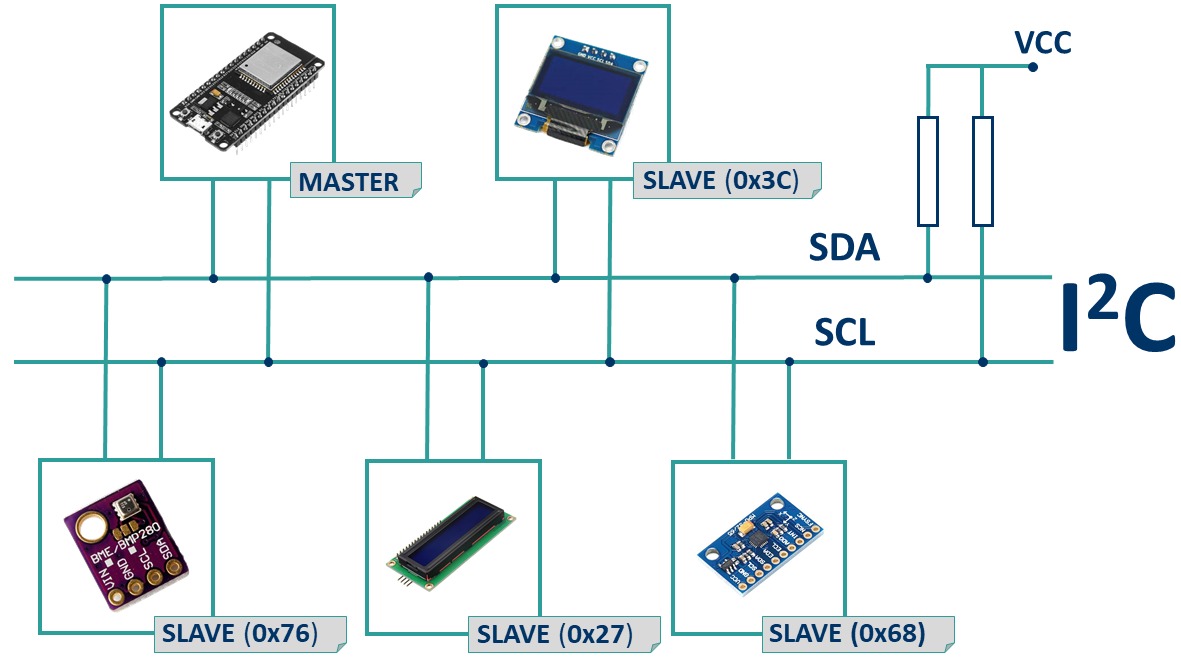
I2C (also known as IIC or TWI - Two-Wire Interface) is a synchronous, serial, half-duplex communication protocol developed by Philips in 1982. It is commonly used for communication between microcontrollers and sensors or memory devices.
An I2C bus uses two signals:
- SDA – Serial Data Line
- SCL – Serial Clock Line
The clock is always generated by the master. Only one device at a time can transmit on the SDA line, making I2C half-duplex.
2. How I2C Works
Unlike SPI, I2C does not need a separate Slave Select line. Instead, each slave has a unique address (usually 7-bit), and communication is always initiated by the Master.
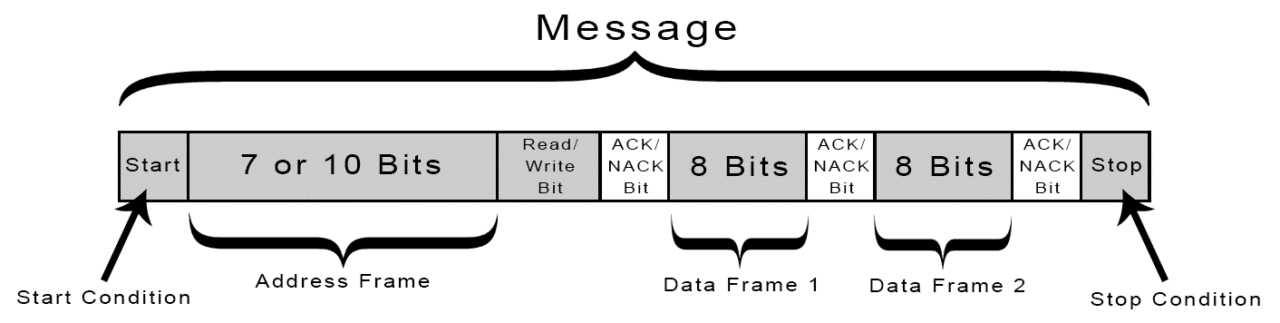
Communication is divided into:
- One Address Frame
- One or more Data Frames
Messages are surrounded by special signals:
- Start Condition
- Stop Condition
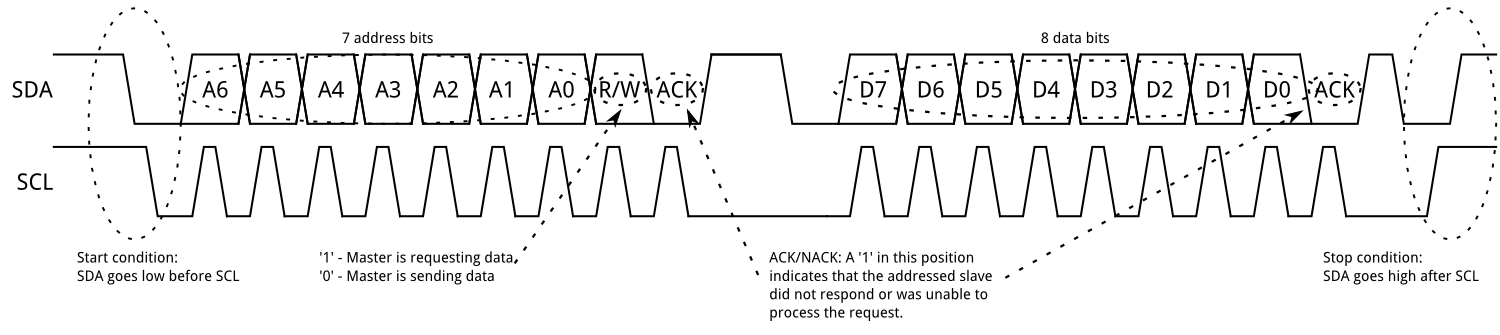
2.1 Start Condition
Before sending the slave's address, the Master must generate a Start Condition:
- While SCL is HIGH, SDA transitions from HIGH to LOW.
This signals all slaves to listen for an address.
2.2 Address Frame
After the start condition, the master sends:
- 7 bits: Slave Address (A6–A0)
- 1 bit: R/W (0 = Write, 1 = Read)
The slave that recognizes its address sends an ACK by pulling SDA LOW during the 9th clock cycle.
If SDA remains HIGH during this 9th clock, it's a NACK.
2.3 Data Frames
If ACK was received, the master proceeds with:
- Writing: Master sends bytes, slave ACKs each.
- Reading: Slave sends bytes, master ACKs each.
To end a read, the Master sends a NACK instead of ACK on the last byte.
Each byte is followed by an ACK/NACK depending on direction.
2.4 Stop Condition
To end communication, the master issues a Stop Condition:
- SDA transitions from LOW to HIGH after SCL is HIGH.
Multiple slaves can share the same bus, but are addressed individually using their unique addresses (typically 7-bit). The LSB of the address frame indicates read (1) or write (0). Once the slave is selected, data transmission begins.
3. I2C Configuration Registers
The ATmega324P microcontroller supports both I2C Master and Slave operation modes.
TWI Bit Rate Register (TWBR)
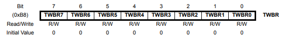
- This register sets the frequency divider that determines the SCL clock speed when in Master mode.
TWI Control Register (TWCR)
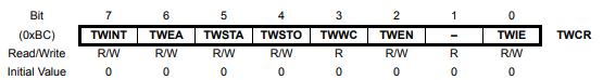
- The control register is used to enable I2C communication, initiate start/stop conditions, acknowledge received data, and check for collisions.
| Bit | Name | Description |
|---|---|---|
| 7 | TWINT | TWI Interrupt Flag (set by HW, cleared by writing 1 in SW) |
| 6 | TWEA | Enable Acknowledge: 1 = send ACK, 0 = NACK (disconnect) |
| 2 | TWEN | Enable TWI module: 1 = enable, 0 = disable |
TWI Status Register (TWSR)
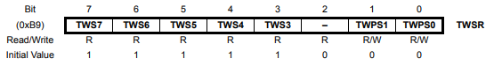
- Indicates current TWI status (start sent, address acknowledged, etc.) and prescaler settings.
TWI Data Register (TWDR)

- Contains the next byte to transmit (TX) or the last byte received (RX), depending on context.
4. Using the I2C Module on AVR
Setting up the I2C module is straightforward — you mainly need to set the clock frequency.
Example: Initialize I2C at 100kHz
void twi_init(void)
{
  // Set prescaler to 1 (TWPS = 00)
  TWSR = (0 << TWPS0);

  // Set bitrate register
  // Formula: TWBR = (F_CPU / SCL_freq - 16) / (2 * prescaler)
  TWBR = 52; // For 12MHz CPU clock and 100kHz SCL
}
However, performing a full I2C transaction is more complex and involves the following steps:
- Set
TWCRto issue a START condition. - Wait for completion (poll
TWCR.TWINT). - Load the slave address into
TWDRand start transmission. - Wait and check for ACK using
TWSR. - Transmit or receive data bytes via
TWDR, with appropriate waiting after each. - Issue a STOP condition using another flag in
TWCR.
5. Pressure Sensor – MPL3115A2
The lab board includes an MPL3115A2 pressure and temperature sensor that communicates via I2C.
I2C Pins for the Sensor:
| I2C Signal | GPIO Pin |
|---|---|
| Enable | PA6 |
| SCL | PC0 |
| SDA | PC1 |
Communication with the sensor requires read/write access to its internal registers via I2C. Before either operation, the register address must be sent.
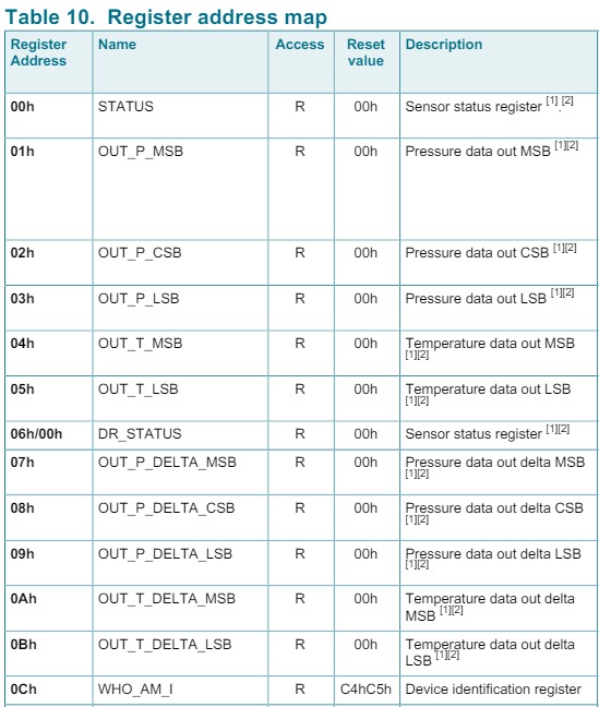
Register map and their respective addresses can be found in the MPL3115A2 Datasheet, section 14.
6. Exercises
- Lab Work
- Homework
Download the code skeleton archive and follow the instructions marked with TODO.
Task 0 – Basic I2C Initialization
Complete the bodies of the functions twi_init, twi_start, and twi_stop in the twi.c file.
💡 Constant definitions can be found in avr-libc util/twi.h
Task 1 – Reading and Writing
Implement the functions twi_read_ack, twi_read_nack, and twi_write in twi.c.
💡 Tip: See Table
23-2, page 268 of the ATmega324P Datasheet for a full example.
Task 2 – Discover Devices on I2C Bus
Implement twi_discover in twi.c. This function should send a read address (SLA_R) to all possible I2C addresses (0–127) and detect which devices respond with ACK.
- Display connected device addresses via serial.
- Make sure to call this function in
main().
💡 Tip: Use the
TWSRregister to check if the slave acknowledged (ACK). See Table23-4, page 275 in the datasheet for status codes.
To send a read or write address:
// Read address
(DEVICE_ADDRESS << 1) | 1

// Write address
DEVICE_ADDRESS << 1
📌 The sensor address is 0x60 → read = 0xC1, write = 0xC0.
Task 3 – MPL3115A2 Pressure Sensor
We will now configure and read from the MPL3115A2 I2C sensor.
Task 3.1 – Initialize Sensor
Complete mpl3115a2_init in mpl3115a2.c. This should be called once in main() before entering the loop.
📌 Set CTRL_REG1 accordingly to operate in pressure mode (make sure the ALT bit is 0).
Task 3.2 – Read Pressure and Temperature
Complete mpl3115a2_read_pressure and mpl3115a2_read_temperature in mpl3115a2.c. Call these in the main loop and print the values over serial.
Section 14 of the MPL3115A2 Datasheet contains register descriptions.
Pressure formula (Q18.2 format):
PRESSURE = (OUT_P_MSB << 12) | (OUT_P_CSB << 4) | (OUT_P_LSB >> 4);
Read Register Sequence
Use the following sequence when reading from a register:
twi_start();
twi_write(DEVICE_ADDRESS << 1);        // SLA + W
twi_write(REGISTER_ADDRESS);           // register to read
twi_start();                           // repeated START
twi_write((DEVICE_ADDRESS << 1) | 1);  // SLA + R

uint8_t data = 0;
twi_read_nack(&data);
twi_stop();
✅ After completing the tasks, you should be able to communicate with the MPL3115A2, detect its address, configure it, and read valid pressure and temperature values.
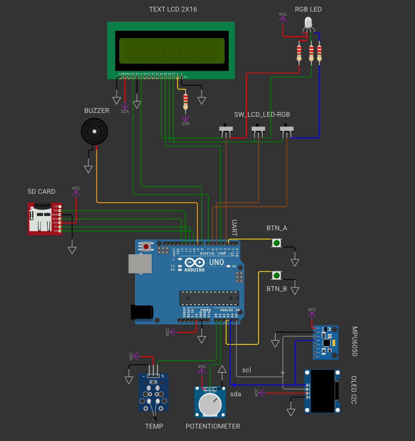
From now on you will be working with Wokwi because its easier to import libraries. The 📥homework skeleton will be the same for all the labs. You don't need to modify the circuit for the homework. You will only change the .c and .h files. The connections to the peripherals wil be different from the ones in the lab development board. For the homework you will work with Arduino Uno (ATmega328P).
Make sure to read the README.md before solving the exercises.
Task 0 – Basic I2C Initialization
Complete the bodies of the functions twi_init, twi_start, and twi_stop in the twi.c file.
💡 Constant definitions can be found in avr-libc util/twi.h
Task 1 – Reading and Writing
Implement the functions twi_read_ack, twi_read_nack, and twi_write in twi.c.
💡 Tip: See Table
23-2, page 268 of the ATmega324P Datasheet for a full example.
Task 2 – Discover Devices on I2C Bus
Implement twi_discover in twi.c. This function should send a read address (SLA_R) to all possible I2C addresses (0–127) and detect which devices respond with ACK.
- Display connected device addresses via serial.
- Make sure to call this function in
main().
💡 Tip: Use the
TWSRregister to check if the slave acknowledged (ACK). See Table23-4, page 275 in the datasheet for status codes.
To send a read or write address:
// Read address
(DEVICE_ADDRESS << 1) | 1

// Write address
DEVICE_ADDRESS << 1
📌 The sensor address is 0x60 → read = 0xC1, write = 0xC0.
Task 3 – MPU6050 accelerometer
To get the data we want from the digital sensor, we need to access its internal registers. The MPU-6500 has some rules when it comes to reading and writing to these registers, that must be extracted from the datasheets. Every sensor has different registers, and different ways of interfacing them, so reading the datasheet is usually required, especially when we don't have the leverage of using already existing libraries for these sensors.
Get the acceleration and angular velocity readings from the sensor.
- Configure the full scale as ±2g for the acceleration and ±1000°/s for the angular velocity
- Read the raw values for the X axis of the accelerometer and print them in a loop.
Read Register Sequence
Use the following sequence when reading from a register:
twi_start();
twi_write(DEVICE_ADDRESS << 1);        // SLA + W
twi_write(REGISTER_ADDRESS);           // register to read
twi_start();                           // repeated START
twi_write((DEVICE_ADDRESS << 1) | 1);  // SLA + R

uint8_t data = 0;
twi_read_nack(&data);
twi_stop();
✅ After completing the tasks, you should be able to communicate with the MPL3115A2, detect its address, configure it, and read valid pressure and temperature values.